As a key thermal insulation material for industrial furnaces and high-temperature equipment, the performance stability of ceramic fibre boards directly affects the operational efficiency and safety of such equipment. However, in practical applications, problems such as cracking, flaking and discolouration frequently occur, leading to increased energy consumption and a shortened service life of the equipment. Today, Mu Yi draws on the latest industry research findings and engineering case studies to systematically analyse the causes and solutions for 15 typical types of failure, providing technical personnel with a practical, actionable guide.
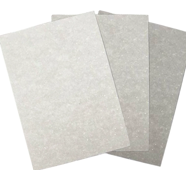
Ceramic Fibre Board
I. Material Cracking: Controlling Stress Concentration at Source
1. Thermal Stress Cracking
Symptoms: Through-cracks propagating along grain boundaries, commonly observed under rapid heating and cooling conditions.
Causes: Non-uniform crystal structure of the ceramic fibre (e.g. mullite crystallisation defects) and insufficient thermal shock resistance.
Solutions:
Material Selection: Prioritise ceramic fibres containing zircon sand additives, as these offer 40 per cent greater thermal shock stability than standard fibres.
Process Optimisation: Limit the heating rate to ≤10 °C/min; during cooling, employ gradient cooling (e.g. 4 hours from 1400 °C to 1000 °C, and 6 hours from 1000 °C to 600 °C).
Structural improvements: Employ a rounded transition design at furnace corners to reduce stress concentration points.
2. Mechanical stress cracking
Phenomenon: Localised spalling, commonly observed near anchoring components.
Causes: Excessively close spacing of anchoring pins (e.g. <150 mm) and excessive mechanical stress applied by the fasteners.
Solutions:
Construction specifications: Control the spacing of anchoring pins to between 200 and 300 mm; use 310S stainless steel; and check the firmness of each pin individually by tapping with a hammer after welding.
Compensation design: Fill the gaps between modules with ceramic fibre blankets folded in half and compressed to a compression ratio of 1:3 to compensate for high-temperature shrinkage.
II. Detachment Issues: Enhancing Structural Stability
3. Localised Detachment
Symptoms: A small number of modules become loose or detach, commonly observed on the furnace roof and side walls.
Causes: Failure to provide expansion joints during installation; insufficient compression of the compensation blanket.
Solutions:
Repair Procedure:
Clear debris from the detached area and weld in new anchor pins;
Lay a ceramic fibre blanket backing (thickness ≥ 50 mm);
Install new modules, filling the gaps with ceramic fibre batt and compacting it;
Spray a high-temperature curing agent (e.g. aluminium oxide sol) to enhance bonding strength.
Case Study: Modules at the corner of a cracking furnace roof in a petrochemical plant had fallen off; the issue was rectified using a layered ceramic fibre blanket structure, and no recurrence has been observed after two years of operation.
4. Extensive Detachment
Symptoms: Collapse of an entire row or large area of modules, often caused by excessive temperatures or chemical corrosion.
Causes: Prolonged operation above the rated temperature (e.g. a 1200°C furnace chamber used for 1300°C conditions), or penetration by molten metal.
Solutions:
Structural Reconstruction:
Demolish the damaged area and clean the steel plate surface;
Install movable compression baffles and fit new modules in a side-by-side configuration;
Fill the gaps with ceramic fibre blanket and spray a curing agent after removing the baffles.
Protection upgrade: Spray an aluminium oxide protective coating onto the fibre surface to prevent the penetration of molten aluminium vapour.
III. Discolouration Issues: Blocking Contamination Pathways
5. Black Spot Discolouration
Symptoms: Long, strip-like black spots on the surface of the insulation layer, commonly seen in glass furnaces.
Cause: High-temperature flue gas escapes through expansion joints, depositing SO₂ and dust within the fibres.
Solutions:
Sealing: Fill expansion joints (width > 10 mm) with zircon-based sealing material; grout fine cracks with refractory mortar.
Airflow isolation: Install a galvanised sheet metal baffle above the fire viewing port to prevent flue gas from directly impinging on the insulation layer.
6. Yellowish-brown discolouration
Symptoms: Uniform yellowish-brown patches on the surface of the insulation layer, most commonly found within the fibreboard.
Cause: The organic binder undergoes a browning reaction at high temperatures.
Solutions:
Material substitution: Select inorganic ceramic fibre boards (such as pure alumina fibre boards) and avoid products containing organic binders.
Construction optimisation: When spraying the fibres, use tap water from the plant premises to prepare the binder, thereby reducing interference from organic impurities in the recirculating water.
IV. Performance Degradation: Delaying the Ageing Process
7. Excessive Shrinkage
Symptoms: A reduction in the thickness of the furnace lining exceeding 10 per cent, leading to a decline in sealing performance.
Cause: Insufficient pre-compression ratio of the material and high-temperature crystallisation causing the fibres to become brittle.
Solutions:
Material Acceptance: Require suppliers to provide modules with a pre-compression ratio of ≥1.2 and a dimensional tolerance of ≤2 mm.
Regular Testing: Use a thermal expansion analyser to measure the material’s coefficient of thermal expansion, ensuring that the glaze’s coefficient is 0.5 × 10⁻⁶/°C lower than that of the body.
8. Reduced Abrasion Resistance
Symptoms: Powdering of the fibre surface, commonly observed in areas subject to gas flow erosion.
Causes: Inconsistent fibre diameters and defects in the crystal structure.
Solutions:
Surface reinforcement: Apply a high-temperature curing agent by spraying to form a protective coating, thereby tripling erosion resistance.
Structural optimisation: Incorporate a layer of high-density fibres (density ≥ 240 kg/m³) in the erosion-prone areas to distribute stress.
V. Installation Defects: Standardising Construction Procedures
9. Loose Anchors
Symptoms: A precursor to module detachment, accompanied by unusual noises or localised overheating.
Causes: Inadequate welding of anchor pins; significant deviations in spacing.
Solutions:
Welding specifications: Use a full-penetration welding process; weld bead height ≥ 3 mm; carry out a hammer test after welding.
Spacing Control: Use a laser positioning device to mark out the lines, ensuring the spacing error at the cross-points of the anchoring pins is ≤5 mm.
10. Insufficient Compression of the Expansion Mat
Symptoms: Gaps between modules widen, allowing flames to penetrate.
Causes: The expansion mat has not been folded in half and compressed, or has been laid in a single layer.
Solutions:
Construction Standards: The expansion blanket must be strictly folded in half and compressed, or laid in two layers; when installing on furnace walls, compress and compact the material from the bottom upwards.
Acceptance Inspection: Use a feeler gauge to measure the gap width, ensuring it is ≤3 mm.
VI. Environmental Corrosion: Establishing Protective Barriers
11. Chemical Corrosion
Symptoms: Powdering of the fibre surface, commonly observed in aluminium processing furnaces.
Cause: High-temperature aluminium vapour penetrates the pores of the fibres, forming low-melting-point eutectic compounds.
Solutions:
Isolation Measures: Lay corundum pads inside the furnace chamber, or use crucibles to isolate the material.
Material Upgrade: Select ceramic fibre containing Cr₂O₃, which improves resistance to aluminium vapour corrosion by 50 per cent.
12. Oxidation Spalling
Symptoms: Flaking of the fibre surface, commonly observed in furnaces and kilns operating under oxidising atmospheres.
Cause: Excessive Fe₂O₃ content in the fibres (>1.5%) accelerates the oxidation reaction.
Solutions:
Material selection: Require suppliers to provide ceramic fibres with an Fe₂O₃ content of ≤0.8%.
Atmosphere control: Introduce nitrogen into the furnace chamber to reduce the oxygen concentration to below 5%.
VII. Operational Damage: Standardising Operating Procedures
13. Damage from Mechanical Impact
Symptoms: Scratches or dents on the fibre surface, commonly observed during the loading and unloading of materials.
Cause: Tools made of excessively hard materials (e.g. metal tools) or rough handling.
Solutions:
Tool Modification: Use wooden or ceramic tools for loading and unloading materials to avoid direct contact with the fibre surface.
Operational Training: Instruct operators to handle materials with care and prohibit striking objects inside the furnace chamber.
14. Thermal Shock Damage
Symptoms: Micro-cracks on the fibre surface, commonly seen following frequent start-up and shutdown of the equipment.
Causes: Concentration of thermal stress caused by sudden rises and falls in temperature.
Solutions:
Operating Standards: Control the heating and cooling rates of the empty furnace to between 5–10 °C/min to avoid exceeding the material’s tolerance.
Preheating: Before starting the furnace, introduce a low-temperature gas flow (<200 °C) to preheat the furnace chamber and reduce temperature differentials.
VIII. Comprehensive Maintenance: Extending Service Life
15. Preventative Maintenance System
Measures:
Routine inspections: Inspect the furnace chamber surface after each use; if micro-cracks are detected, apply high-temperature repair compound immediately.
Periodic calibration: Verify the accuracy of thermocouples quarterly to ensure the temperature control system has an error of ≤±2°C.
Thorough Maintenance: Test the earth resistance annually (which should be <4 Ω) and clear ash build-up from the furnace chamber to prevent short circuits.
Conclusion
Troubleshooting issues with ceramic fibre boards requires a multi-faceted, coordinated approach covering material selection, installation standards, environmental control and operational management. Through systematic solutions, the cracking rate can be reduced to below 5 per cent, the detachment rate kept within 2 per cent, and discolouration issues virtually eliminated. It is recommended that companies maintain production logs, recording the process parameters and maintenance records for each batch, to provide data support for continuous optimisation. In the future, with the widespread adoption of nano-modification technology and self-healing coatings, the reliability of ceramic fibre boards will be further enhanced, providing more stable solutions for high-temperature industrial applications.