In applications such as industrial furnaces, heat treatment equipment and high-temperature pipework, ceramic fibre modules have become the mainstream insulation material due to their lightweight, high-performance and easy-to-install characteristics. However, the selection of density and insulation thickness must be closely aligned with operating conditions; if these parameters are configured incorrectly, it may lead to increased energy consumption, a shortened service life of the equipment, or even safety hazards. Today, Mu Yi will draw upon practical case studies and technical specifications from both domestic and international sources to systematically analyse strategies for matching density and thickness, providing enterprises with practical technical guidance.
I. Selecting Density: Striking a Balance Between Performance and Cost
1. The Impact of Density on Thermal Performance
The thermal conductivity of ceramic fibre modules follows a ‘first-decrease-then-increase’ trend as density increases. When the density is below 180 kg/m³, insufficient contact points between fibres and excessive porosity lead to intensified convective heat transfer; when the density exceeds 240 kg/m³, the fibre fracture rate rises, and the increased number of solid contact points forms ‘thermal bridges’, which in turn drive up the thermal conductivity. During the refurbishment of a heating furnace at a steelworks, adjusting the density of the furnace roof modules from 260 kg/m³ to 230 kg/m³ reduced surface heat loss by 12 per cent, resulting in annual energy savings of over 2 million yuan.
2. Logic for Matching Density to Operating Conditions
High-temperature scenarios (≥1,200 °C): A density of 220–240 kg/m³ is recommended. For example, roof modules in glass melting furnaces must balance resistance to airflow erosion with low thermal conductivity; one enterprise reduced furnace roof temperature fluctuations from ±30 °C to ±15 °C through density optimisation.
Medium- and low-temperature scenarios (800–1,200 °C): A density of 200–220 kg/m³ is sufficient to meet requirements. For example, sidewall modules for a chemical reactor were designed with a density of 210 kg/m³, reducing material costs by 15 per cent whilst maintaining thermal insulation performance.
Special medium environments: In sulphur-containing atmospheres, the upper limit of module density must be controlled. Through density optimisation, a petrochemical enterprise reduced the hydrogen sulphide permeation rate in its cracking furnace modules to 0.03 g/m²·d, well below the national standard requirement of 0.05 g/m²·d.
3. Co-design of Module Structure and Density
Z-shaped modules: The number of folded layers must be matched to the density. A certain enterprise controlled the density of a 16-layer folded module at 225 kg/m³, improving construction efficiency by 40 per cent whilst eliminating the risk of collapse.
U-shaped modules: The spacing of support beams must be adjusted according to density. A certain heat treatment furnace reduced the compressive deformation of the modules by 25 per cent by optimising the support beam spacing to 300 mm.
Hard-soft composite modules: The thickness of heavy-duty facing bricks must be designed in conjunction with the density of the fibre layer. A certain enterprise utilised a combination of 10 mm facing bricks and a 220 kg/m³ fibre layer, achieving dual improvements in maintenance convenience and thermal insulation performance.
II. Design of Insulation Thickness: The Balance Between Economy and Performance
1. Methodology for Thickness Calculation
Economic Thickness Method: Targeting a payback period of ≤3 years, a combined heat and power (CHP) boiler reduced the payback period for its insulation investment to 2.8 years through thickness optimisation.
Heat Loss Limit Method: This must be combined with surface temperature control requirements. After a petrochemical pipeline adopted 60 mm thick modules, the surface temperature dropped from 120 °C to 65 °C, meeting safety standards for human contact.
Dynamic Simulation Method: Through ANSYS Workbench simulation, a glass kiln found that increasing the thickness of the furnace roof from 80 mm to 100 mm reduced heat loss by 18 per cent; however, the benefits diminished when the thickness exceeded 120 mm.
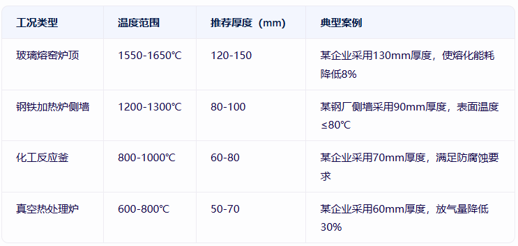
2. Recommended Thickness Values for Typical Operating Conditions
. Optimisation Strategies for Composite Structures
Gradient density design: A glass furnace utilised a ‘220 kg/m³ + 200 kg/m³’ dual-layer module, reducing the total thickness by 15 per cent whilst improving thermal insulation performance by 10 per cent.
Nanofibre Reinforcement Layer: By embedding a 5 mm layer of nanofibres in high-temperature zones, a particular company reduced thermal conductivity to 0.08 W/(m·K), a 25 per cent reduction compared to conventional materials.
Application of Moisture-Resistant Coating: By applying a 0.2 mm silicone resin coating under humid operating conditions, a particular company reduced the fibre moisture influence coefficient from 0.8 to 0.3, extending the service life of the modules by two years.
III. Key Points for Project Implementation: End-to-End Control from Design to Acceptance
1. Customised Module Production
Fibre length control: By using fibres 80–130 mm in length, a particular company optimised fibre length to reduce the breakage rate from 48 per cent to 12 per cent.
Anchoring system design: A glass furnace utilised a ‘metal tie rod + steel mesh’ anchoring structure, increasing the module’s wind pressure resistance to 2 kPa.
Precast Component Integration: A heat treatment furnace utilised bolted connections between the modules and the furnace shell steel plates, increasing construction efficiency by 50 per cent whilst eliminating thermal expansion cracks.
2. Construction Quality Control
Compression Ratio Control: A company used a hydraulic press to maintain the compression ratio between 15 per cent and 20 per cent, ensuring the module density deviation was ≤±5 per cent.
Joint Treatment: By employing a ‘staggered joints + high-temperature mastic’ process, a certain project reduced heat loss at the joints to within 5 per cent of the total heat loss.
Humidity Monitoring: The humidity of the construction environment must be ≤85 per cent; a certain enterprise used dehumidification equipment to reduce the modules’ moisture content from 5 per cent to 1.5 per cent.
3. Acceptance and Maintenance Standards
Heat Flux Density Testing: Using infrared thermal imaging scans, a certain enterprise’s acceptance standard is a heat flux density of ≤80 W/m².
Service Life Prediction Model: Based on the Arrhenius model, a certain enterprise predicts a module service life of 8 years, which is 3 years longer than that of traditional materials.
Dynamic Optimisation Mechanism: A certain enterprise has established a database of operating conditions and updates the density–thickness matching parameters quarterly to achieve continuous improvements in energy-saving benefits.
Conclusion
The selection of density and thickness for ceramic fibre modules must adhere to the principles of ‘operating condition adaptation, performance priority and cost control’. Through density gradient design, optimisation of composite structures and end-to-end quality control, enterprises can reduce overall costs whilst meeting thermal performance requirements. It is recommended that a three-dimensional database covering ‘operating conditions, materials and construction’ be established, combined with digital twin technology to achieve dynamic optimisation, thereby providing precise technical support for energy-saving retrofits of industrial furnaces.