In the waste-to-energy sector, the high-temperature protection of flue gas ducts presents a key technical challenge to ensuring the safe operation of the system. Incineration flue gas temperatures can reach 1,100–1,400 °C and contain highly corrosive components such as HCl, SO₂, NOx and dioxins; traditional refractory materials are prone to spalling and failure due to thermal stress, chemical erosion and dust abrasion. Ceramic fibre boards, owing to their excellent fibre network structure and inorganic chemical stability, are gradually becoming the mainstream solution for the protection of high-temperature flue gas ducts.
I. The Challenges Posed by High-Temperature Flue Gas Environments to Protective Materials
1. The Combined Effects of Thermal Stress and Mechanical Damage
Temperature fluctuations in waste incineration flue gas can reach ±200 °C/h, with temperature gradients on duct walls exceeding 300 °C/m. A case study at a waste incineration plant showed that, after two years of operation, pipes lined with traditional refractory castables exhibited localised spalling layers 3 mm thick. Analysis revealed that thermal shock cycles had caused the crack density within the castable to reach 0.8 cracks per cm², far exceeding its critical value (0.3 cracks per cm²).
2. Chemical erosion caused by acidic gas corrosion
The concentration of HCl in flue gas can reach 500–1,200 ppm, whilst that of SO₂ ranges from 100 to 300 ppm. At high temperatures of 800 °C, these gases react with the inner walls of the pipework:
HCl corrosion: 2Al₂O₃ + 6HCl → 2AlCl₃ + 3H₂O (corrosion of the alumina-based protective layer)
SO₂ Conversion: SO₂ + 1/2O₂ → SO₃ (forms H₂SO₄ acid mist with water vapour)
Simulation experiments conducted in a laboratory have shown that, in flue gas containing 500 ppm HCl, the corrosion rate of ordinary refractory bricks reaches 0.3 mm/year, whilst that of ceramic fibre boards is less than 0.05 mm/year.
3. Physical wear caused by dust abrasion
Fly ash particles in flue gas have a hardness of 6–7 on the Mohs scale; at a flow velocity of 15 m/s, the abrasion rate on the inner wall of the duct can reach 0.1 mm per thousand hours. Actual measurements at a power station showed that after 5,000 hours of operation, the inner wall wear depth of a duct lined with corundum-mullite bricks reached 1.2 mm, whereas ceramic fibre boards, through the oriented arrangement of their fibres and their self-repairing properties, reduced the wear rate to 0.02 mm per thousand hours.
II. Protective Mechanism and Material Advantages of Ceramic Fibre Boards
1. Thermal Barrier Mechanism of the Nanoscale Fibre Network
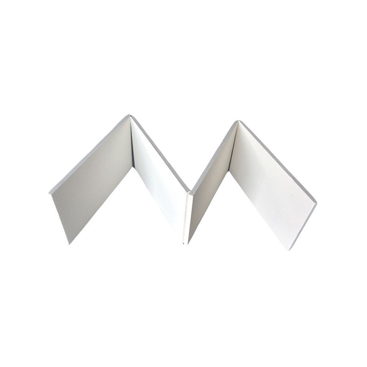
Ceramic fibre boards are formed by a three-dimensional interlacing of SiO₂-Al₂O₃ fibres with diameters of 2–5 μm; they have a porosity as high as 95 per cent and a thermal conductivity of merely 0.08 W/(m·K). The fibre network, formed through a double-sided needling process, effectively lengthens the heat conduction path, reducing the heat flux density on the pipe wall caused by flue gas at 1,000 °C to 15 kW/m², which is only one-third that of traditional castables.
2. Inorganic chemical stability and corrosion resistance
The main constituents of ceramic fibre boards—SiO₂ (60–70 per cent) and Al₂O₃ (25–35 per cent)—form a dense SiO₂–Al₂O₃ glass phase at high temperatures, with an acid resistance coefficient (the reciprocal of the HCl erosion rate) of 1,200, which is 20 times that of clay bricks. Furthermore, the Si–OH bonds on the fibre surface can undergo a passivation reaction with corrosive gases, forming a protective film 0.1–0.2 μm thick.
3. Self-healing capability through fibre fracture and reorganisation
When fibre boards are subjected to impact loads, localised fibre fracture triggers stress redistribution, with surrounding fibres bearing the load via a bridging effect. An accelerated ageing test demonstrated that, following 100 thermal shock cycles (ΔT = 1000 °C/room temperature) at 1000 °C, the residual strength retention rate of ceramic fibre boards reached 85 per cent, whilst that of corundum bricks was only 42 per cent.
III. Key Technologies and Implementation Pathways for Engineering Applications
1. Design of Composite Protection Systems
In flue gas ducts, a ‘ceramic fibre board + anchoring elements + protective coating’ sandwich structure is typically employed:
Base layer: 150 mm thick ceramic fibre board (density 200 kg/m³)
Intermediate layer: V-shaped stainless steel anchoring elements (spaced at 300 × 300 mm)
Surface layer: 5 mm thick phosphate-bonded high-alumina wear-resistant coating
A refurbishment project at a waste incineration plant demonstrated that this system reduced the external wall temperature of the flue from 280 °C to 85 °C, cutting heat loss by 75 per cent and yielding annual energy savings in excess of 2 million yuan.
2. Moulding Technology for Irregular Shapes
For complex sections such as flue elbows and tees, a ‘wet vacuum moulding + CNC cutting’ process has been developed:
Solid content of the fibre slurry is controlled at 35–40 per cent
Moulding pressure: 0.6–0.8 MPa
Drying profile: 120 °C/2 h → 250 °C/3 h → 600 °C/5 h
This technology enables the production of pre-fabricated elbow components with a radius of R = 1.5D, achieving dimensional accuracy of ±1 mm and improving installation efficiency by 40 per cent.
3. Intelligent Monitoring and Maintenance System
Through the installation of fibre Bragg grating sensors, the following parameters can be monitored in real time:
Temperature (accuracy ±1 °C)
Strain (accuracy ±1 με)
Crack propagation (resolution 0.01 mm)
Data from a pilot project shows that this system has extended the preventive maintenance cycle from 6 months to 24 months and reduced maintenance costs by 60 per cent.
IV. Analysis of Typical Case Studies: The Transition from Laboratory to Industrial Application
1. Refurbishment of a Municipal Waste-to-Energy Plant
Background: The original pipework utilised heavy-duty refractory bricks, which exhibited extensive spalling after three years of operation, necessitating a shutdown for repairs.
Solution:
Remove the original lining and clean the substrate
Install 180 mm thick ceramic fibre boards (containing 20% zirconia fibre)
Apply a 1 mm thick nano-ceramic coating to the surface
Results:
The outer wall temperature of the duct fell from 320°C to 95°C
Heat loss was reduced from 18 per cent to 5 per cent
The maintenance interval was extended from 2 years to 8 years
2. New Construction Project at a Hazardous Waste Incineration Centre
Technical Highlights:
Use of gradient-functional ceramic fibre boards (outer layer with 95 per cent Al₂O₃ content, inner layer with 70 per cent)
Integration of an SCR denitrification catalyst coating
Development of a modular installation process (Weight per panel ≤ 25 kg)
Operational Data:
Nitrogen oxide removal efficiency reached 92 per cent
Dioxin removal rate: 99.99 per cent
System pressure drop reduced by 40 per cent
V. Technological Outlook: Towards Intelligence and Multifunctionality
With the advancement of Industry 4.0 and carbon neutrality targets, ceramic fibre boards are evolving in the following directions:
1. Self-sensing and self-healing material systems
Through the incorporation of shape-memory alloy fibres and microcapsule repair agents, the following are achieved:
Automatic repair triggered when crack width exceeds 0.1 mm
Repair efficiency > 90 per cent
Repair time < 24 hours
2. Multifunctional integrated design
Development of composite fibre boards that combine:
Sulphur and nitrogen oxide removal catalytic functions
Infrared radiation enhancement (emissivity > 0.9)
Electromagnetic shielding capabilities (attenuation > 60 dB)
3. Digital Manufacturing Technologies
The application of 3D printing technology enables:
Controlled orientation of fibres (angular accuracy ±1°)
Gradient porosity design (continuously adjustable between 50–95 per cent)
Integrated moulding of complex structures (dimensions as small as 0.5 mm)
Conclusion
The application of ceramic fibre boards in waste incineration flue gas ducts essentially represents a deep integration of materials science, thermal engineering and smart manufacturing. Through the regulation of the microstructure of the fibre network, the design of materials with inorganic chemical stability, and the integrated application of smart monitoring technologies, engineering challenges such as high-temperature corrosion and thermal stress damage can be systematically resolved. With breakthroughs in the research and development of ultra-high-temperature ceramic fibres (such as HfB₂ fibres, with a melting point > 3250°C) and smart sensing fibres, future flue gas duct protection systems will offer greater reliability, lower energy consumption and a longer service life, providing a solid foundation for the green development of the waste-to-energy sector.