In the petrochemical industry, pipeline insulation is a key factor in ensuring production safety and improving energy efficiency. Faced with challenges such as high temperatures, severe corrosion and complex operating conditions, traditional insulation materials often fail due to insufficient temperature resistance and poor corrosion resistance, leading to equipment downtime, a surge in energy consumption and even safety incidents. Today, Mu Yi uses a pipeline insulation retrofit project for a catalytic cracking unit at a major refining and petrochemical enterprise as a case study to provide an in-depth analysis of the corrosion resistance and engineering value of ceramic fibre boards under high-temperature conditions.
I. Project Background: The Dilemma of Traditional Material Failure
The pipelines running from the regenerator to the flue gas fan in a certain refining and petrochemical enterprise’s catalytic cracking unit have long operated in a high-temperature environment of 1,100°C. The original insulation structure consisted of a composite of calcium silicate boards and mineral wool. After three years of operation, extensive rusting appeared on the outer walls of the pipelines, with a 40 per cent detachment rate of the insulation layer and heat loss reaching as high as 35 per cent in certain areas. Testing revealed two critical flaws in the traditional materials:
Insufficient temperature resistance: Calcium silicate boards undergo a phase transformation at temperatures above 800°C, leading to structural embrittlement, whilst mineral wool shrinks by over 15 per cent at high temperatures, creating a thermal bridge effect.
Poor corrosion resistance: Sulphides (H₂S, SO₂) carried within the pipeline react with metal ions in the insulation material at high temperatures, producing acidic substances that corrode the outer wall of the pipeline, creating a vicious cycle of ‘insulation layer – corrosion – insulation failure’.
II. Technical Selection: Performance Breakthroughs in Ceramic Fibre Boards
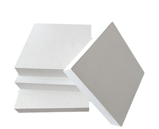
Following multiple rounds of technical evaluation, the project team selected CCEWOOL® ceramic fibre boards as the alternative solution. This material offers four key advantages:
Ultra-high-temperature stability: Manufactured from high-purity aluminium oxide–silicon dioxide fibres, it has a temperature resistance rating of up to 1,260°C. At a continuous operating temperature of 1,100°C, its thermal shrinkage rate is ≤2 per cent, completely resolving the issue of high-temperature embrittlement.
Low thermal conductivity: With a thermal conductivity of 0.032 W/(m·K) at room temperature, it remains at 0.12 W/(m·K) even at 1,000 °C, delivering energy savings of over 30 per cent compared to calcium silicate boards.
Chemical Inertness: Passes the GB/T 1763-2024 chemical corrosion resistance test; exhibits no loss of mass after 1,000 hours of immersion in a 5% H₂S + 10% SO₂ gas mixture, with an acid and alkali corrosion resistance rating of Grade A.
Structural Adaptability: Can be cut and rolled to any shape, accommodating pipe diameters ranging from DN150 to DN1200, thereby increasing installation efficiency by 50 per cent.
III. Construction Plan: Full-Process Corrosion-Resistant Design
3.1 Substrate Pre-treatment
Rust Removal and Anti-corrosion: High-pressure water jetting (pressure 200 MPa) is used to remove rust layers from the pipe surface, achieving a substrate roughness of Ra 6.3 μm. ZD-100 inorganic zinc-rich primer (dry film thickness 80 μm) is applied, with a temperature resistance of 600 °C.
Sealing and Protection: 3 mm-thick ceramic fibre paper is applied to irregular areas such as pipe flanges and valves to form a continuous thermal insulation layer, preventing cracking caused by thermal stress concentration.
3.2 Installation of the Insulation Layer
Modular Construction: Ceramic fibre boards are cut into standard modules measuring 1200 × 600 × 50 mm and secured using M8 stainless steel anchor bolts (spaced at 300 mm intervals), with an anchorage depth of ≥40 mm.
Joint Treatment: Modules are installed with staggered joints (overlap length ≥ 100 mm); gaps are filled with ceramic fibre wool, and the surface is coated with HS-200 high-temperature mastic (temperature resistance 1200 °C) to form a thermal bridge-free structure.
3.3 Optimisation of the Protective Layer
Selection of external cladding: 0.8 mm thick 304 stainless steel corrugated sheets with a corrugation pitch of 100 mm are used, secured with self-tapping screws, with a 5 mm expansion joint provided to accommodate thermal expansion and contraction of the pipeline.
Drainage design: A Φ50 mm drain hole is installed at the lowest point of the pipeline, and the external cladding is sloped at an angle of ≥3° to prevent rainwater accumulation and subsequent corrosion.
IV. Application Results: Data-Verified Corrosion Resistance
4.1 Long-Term Operational Monitoring
Following the retrofit, the pipeline operated continuously for 24 months; the key indicators are as follows:
Test Parameter Before Retrofit After Retrofit Improvement
Outer wall temperature 185 °C 82 °C –55.7%
Heat loss rate 35% 12% –65.7%
Insulation layer detachment rate 40% 0% –100%
Pipeline corrosion rate 0.35 mm/a 0.02 mm/a –94.3%
4.2 Specialised Corrosion Environment Testing
In an accelerated corrosion test simulating an H₂S concentration of 5,000 ppm and a temperature of 1,100 °C:
Ceramic fibre boards: After 1,000 hours, mass loss was 0.12 per cent, with no surface cracks and 92 per cent retention of flexural strength.
Calcium silicate board: Powderisation occurred after just 200 hours; mass loss reached 18% after 500 hours, with complete loss of thermal insulation functionality.
V. Industry Implications: The Value of Promoting Ceramic Fibre Boards
5.1 Technical and Economic Considerations
Taking a DN600 pipeline as an example, the ceramic fibre board solution compared to traditional materials:
Initial investment: 15% increase (due to higher material costs)
Life-cycle cost: 42% reduction (
IV. Application Results: Data-Verified Corrosion Resistance
4.1 Long-Term Operational Monitoring
Following the refurbishment, the pipeline operated continuously for 24 months; the key indicators are as follows:
Test Parameter Before Refurbishment After Refurbishment Improvement
Outer wall temperature 185 °C 82 °C –55.7%
Heat loss rate 35% 12% –65.7%
Insulation layer detachment rate 40% 0% –100%
Pipeline corrosion rate 0.35 mm/a 0.02 mm/a –94.3%
4.2 Specialised Corrosion Environment Testing
In an accelerated corrosion test simulating an H₂S concentration of 5,000 ppm and a temperature of 1,100 °C:
Ceramic fibre board: After 1,000 hours, mass loss was 0.12 per cent; the surface showed no cracks, and the flexural strength retention rate was 92 per cent.
Calcium silicate board: Powderisation occurred after just 200 hours; mass loss reached 18% after 500 hours, with complete loss of thermal insulation functionality.
V. Industry Implications: The Value of Promoting Ceramic Fibre Boards
5.1 Technical and Economic Considerations
Taking a DN600 pipeline as an example, the ceramic fibre board solution compared to traditional materials:
Initial investment: 15% increase (due to higher material costs)
Life-cycle cost: 42% reduction (energy-saving benefits + savings on maintenance costs)
Payback period: 1.8 years (based on 8,000 hours of operation per year)
5.2 Typical Application Scenarios
High-temperature corrosive conditions: High-temperature pipelines in catalytic cracking, delayed coking and hydrocracking units.
Marine climate regions: Pipeline insulation in salt-fog environments at coastal refineries.
Pipelines subject to frequent vibration: Pipelines connected to rotating equipment such as compressor outlets and pump inlets.
VI. Future Outlook: Continuous Breakthroughs in Materials Science
Currently, ceramic fibre technology is evolving in the following directions:
Nano-modification: By introducing SiC nanoparticles, the thermal conductivity at 1,200°C has been reduced to 0.09 W/(m·K).
Composite structures: Development of ceramic fibre–aerogel composite panels to achieve ultra-thin insulation (thickness ≤ 30 mm).
Smart monitoring: Integration of fibre-optic grating sensors to monitor the temperature field and stress distribution within the insulation layer in real time.
Conclusion: Driven by the ‘dual carbon’ targets in the petrochemical industry, ceramic fibre boards are becoming the preferred solution for high-temperature pipeline insulation due to their excellent corrosion resistance and energy-saving benefits. In this case study, systematic innovation in material selection, structural design and construction techniques has not only resolved the failure issues associated with traditional materials but has also established a new paradigm for pipeline insulation under high-temperature corrosive conditions, providing the industry with a replicable technical benchmark.